1962 Chevrolet Corvette Restomod
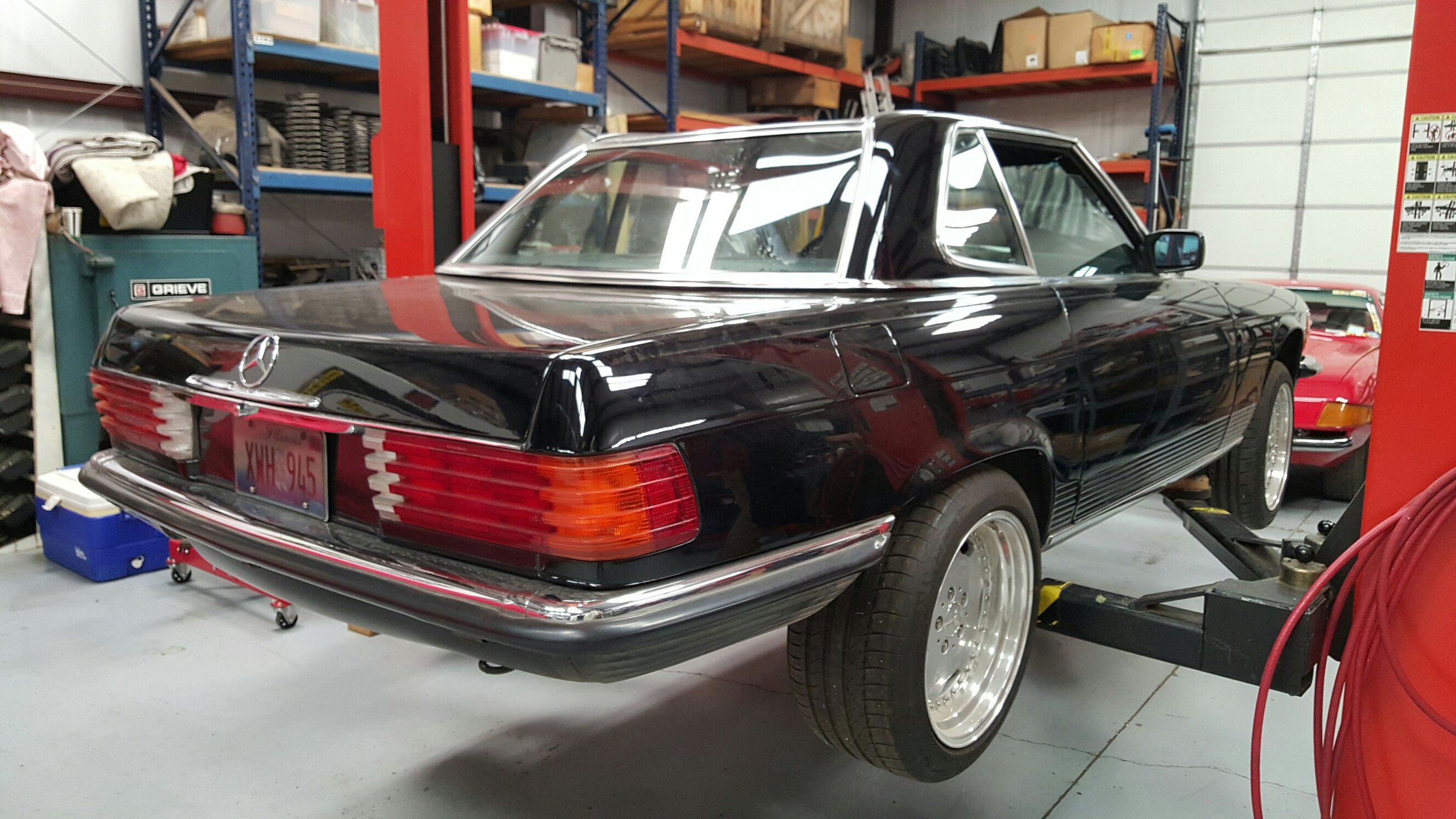
Project Overview: This project came to Carobu as a running car. The body had been painted but much of the assembly needed to be completed. Our task was to finish the mechanicals, which included rebuilding the engine for more power. In addition to the engine rebuild, we upgraded the suspension for better handling, rebuilt the 4-speed manual transmission and installed the exhaust system.

The goal was to have the car look close to stock, but with a lot more power under the hood. The engine compartment had to look concourse correct with the exception of the headers.

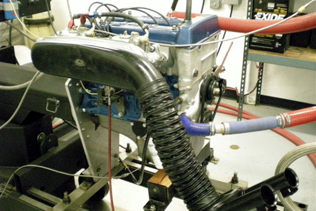
The engine in the car was a period 327 that was rated at 300 HP by the factory. The owner wanted to dyno test the engine before rebuilding into a more powerful version so that he would know what the power gains were. Getting a baseline power figure is always a good idea from a developmental point of view most importantly, but also from a basic curiosity angle as well. Typical for engines from the 1960s, the SAE gross power rating that the factory claimed was nowhere close to what the motor was actually putting out. When it was tested on the dyno, the stock engine peaked out at 215 HP @ 4,300 rpm- not exactly a ball of fire.

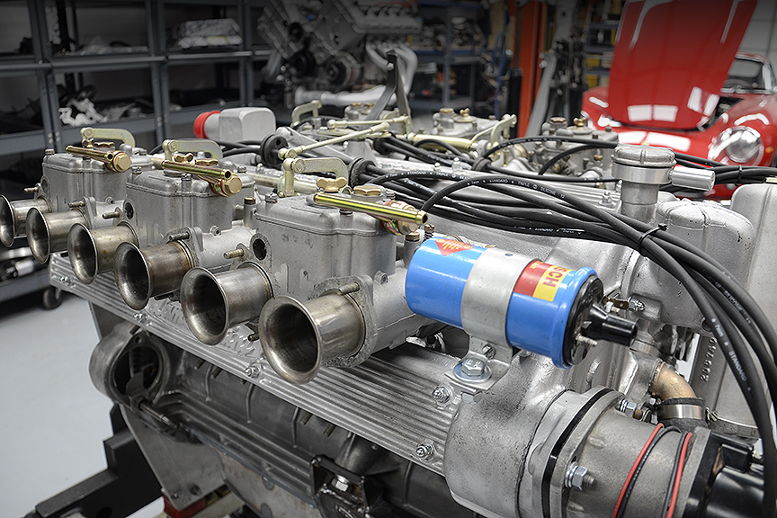
The engine build was dictated by several constraints. The iron heads were retained, as well as the factory intake manifold and carburetor setup. On the other hand, we were free to use any camshaft grind, as long as the car retained it's streetability. The plan was to rebuild and port the iron heads and then install larger 2.02”/1.60” valve sizes, screw-in head studs, 1.6 roller rockers and better quality valve springs. Keith Black hypereutectic pistons would give a fuel-friendly 9.5:1 compression ratio.  A Comp Cams 270H hydraulic camshaft was chosen as the appropriate cam for this set-up. For an intake manifold, we went with a visually period correct aluminum Chevy dual plane high-rise version topped by an original rebuilt Carter AFB carburetor.

The head porting turned out well and yielded a 16% increase in flow on the intake side and a 33% increase in flow on the exhaust side. The block was line-bored, decked bored .040” oversize and then plate-honed to size.

The crankshaft was Magnafluxed to ensure there were no cracks in it and then polished. The connecting rods were shot-peened and polished and installed with new ARP bolts. The entire rotating assembly was precision balanced like all of our engines are.

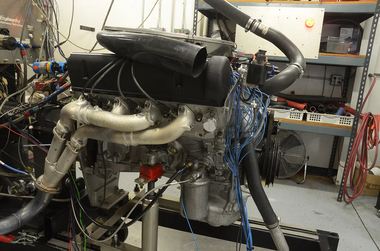
During the dyno testing, the nice surprise was the very flat torque curve. Final HP was way over 300 at 322 HP @ 5,700 rpm. This was a nice increase and definitely made the client very happy. Below is the before and after dyno graph; over one hundred additional ponies!

Carobu Engineering: Ferrari and High Performance Engine Specialists, high performance engine building dyno testing and tuning

After the dust settled, the engine was installed in the chassis along with the transmission. A new suspension replaced the worn-out original parts and a new but original looking exhaust system was attached to the headers. During his test drive, the owner came back with a huge grin on his face saying that the car was wild to drive now. He got his wish!


Mercedes Benz 190SL Vintage Racecar

Project Overview:  The goal of this engine build was to make the maximum power possible within the limits of vintage racing rules, which usually keep modifications and upgrades to a minimum and as close to original as possible. The customer also wanted to have an engine with good mid range torque.

Getting the maximum displacement possible out of the motor was the first thing we focused our energy on. We accomplished this by combining the block of a Mercedes 230 4-cylinder engine that has a 94-mm bore with the crankshaft from a Mercedes 220 engine, which has a 92.4-mm stroke. The combination of the block and crankshaft yielded a displacement of 2,566-cc. The block was rebuilt with forged racing pistons with a relatively high 10.25:1 compression ratio. The internal components were also dynamically balanced. To prevent oil starvation at high RPMs and around fast corners, special oil baffles were installed in the oil pan. An aluminum flywheel with a Tilton racing clutch finished off the engine.


The 190SL cylinder head was flow tested both with and without the intake manifold and carburetor installed. This information was used in our engine simulation program to help determine camshaft profiles for the intake and exhaust systems. Additionally, all of the valves, seats, guides and valve train parts were replaced with brand new items. Intake port dividers were installed for better airflow and the head itself was ported for better air flow.

After careful assembly, the engine was installed on a DTS dyno and carefully broken in before we could begin running it under load at higher RPMs. After that, several dyno runs were performed in order to find the best combination of carburetor tuning and ignition advance that would produce the most possible horsepower and torque.

The result was an impressive 165-hp and 175 lb-ft of torque. This is a significant gain over the stock power rating, which is 105-hp and 105 lb-ft of torque.

Once it was installed back in the car, the engine raced successfully for many seasons in local vintage races, performing very well along the way.

Lotus Elan 1600 Twin Cam

The goal of this engine build was to make 130 HP in a still streetable package. This meant that the camshaft selection and head flow would be critical in this small displacement engine.

As has been the story in the past over and over, this particular engine came to us after having been worked on by a marque "expert" and it was a mess! Luckily, the engine build hadn’t been completed yet as the previous shop let it sit for over a year without working on it before it was pulled out of the shop by the frustrated owner. And, pretty much all the work that had been done needed to be redone or undone. New 10.2:1 forged pistons were ordered to replace the ones that were in the block, but the block itself was salvageable. The head needed everything.

Part of our build mandate was to convert the head to Big Valve specification. While we were at it, some porting was done as well. This worked out well; the intake flow at 28” went from 142.6 cfm @ 0.400” lift to 156.2 cfm. On the exhaust side, the change was less (the valve size didn’t change), 109.1 cfm to 116.5 cfm at the same specs.

For the camshaft, a moderate duration, higher lift cam was chosen. This cam, known as a 114 profile, has 243° of duration @ 0.050” lift and a maximum lobe lift of 0.413”. Fitting this cam required some special valve train parts and cam lobe relieving on the head.

Lotus Elan high performance engine rebuild and development

Basic assembly of this small 4 cylinder engine is straight forward and soon it was ready for the dyno.

After the normal break-in procedure is completed, we were able to start fine tuning the engine to get the most power from it while ensuring it ran perfect. One thing that we insist on at Carobu is dyno tuning the engine with the air filter and muffler system installed that will fitted to the engine when it is back in car. This allows us to tune the air/fuel curve so that it will not change when the car is back on the road.

Lotus Elan high performance engine rebuild and development

Lotus Elan high performance engine rebuild and development

The twin Cam engine responded very well to the modifications that we performed on it and produced the required power output (see graph below).

1986 Mercedes Benz 560SL

The starting point of this project was a very nice Mercedes 560SL that had a rebuilt “improved” engine done by a so-called expert Mercedes tuning shop. The owner of the car was not happy with the results, which had a poor idle quality and soggy bottom-end power. The mandate was to improve the power output, calm down the idle and fatten-up the torque curve for additional performance. We agreed that these were all important goals that we could accomplish.

So that there would be a scientific basis for gauging future improvements, the car’s owner approved removing the engine from the car and dyno testing it on our engine dyno in order determine how much power the engine had before we rebuilt it.

While the concept of testing it on the dyno was simple, getting the engine to run on the dyno required a lot of work due to the various electronic/fuel injection systems that all had to operating properly to obtain an accurate power reading. In the end, the existing engine from the alleged Mercedes tuning specialist generated 252-hp at 5,100 rpm and 291 lb-ft of torque at 4,100 rpm. Both these numbers seemed weak to us. The stock V8 560SL engine is rated at 227-hp by the factory so the above initial dyno numbers were not very impressive (see graph below).

We knew that the other shop had installed a more aggressive camshaft, ported the heads to AMG specs and added a full European exhaust system. They claimed over 300 HP but had no dyno graph to back up the claim. It is common knowledge that Mercedes made more powerful versions of the stock 560 engine (not for the USA) that made 300 HP. We didn't understand why this supposedly tuned engine was such a dog.

At this point we received the OK from the owner to tear the engine down and find out what was inside. Much to our surprise, the engine had stock, low-compression pistons (9:1) and one cylinder head that had been ported but the other one was left stock! This was a shocker.

The existing camshaft that was in the engine was put on our camshaft digitizer so that we could determine the specifications. It had the following specs: Intake- 237.2° @ .050” and maximum lift of 10.7 mm. Exhaust- 243.6° @ .050” and maximum lift of 11.15 mm. Compare that to the stock cam specs: Intake/exhaust 192° @ .050” and maximum lift of 10.7 mm. Basically, this performance cam had much more duration, but only a small amount of added lift improvement over stock. Based on past experience with Bosch CIS fuel injection systems, we knew that the idle would not be as stable with this amount of cam duration/overlap, so a new cam would be needed, but the owner wanted to keep this cam set and go to an EFI injection system.

The next step involved flow-testing the cylinder heads. This would be a nice comparison of stock heads versus AMG-ported heads as we conveniently had both types on hand thanks to the previous engine builder. The results proved interesting as there wasn’t much difference between the two! While we were checking out the heads, we were measuring all of the basic engine dimensions so we could start building a relatively accurate model to use for simulation work. Our program is ‘Performance Trends Engine Analyst Pro Enterprise Edition’ and over the years it has proven very helpful to finding power in various engines before actually beginning the engine building process.

One of the areas that we knew could be improved was the intake manifold. The standard runners are pretty convoluted and the plenum volume is small, both of which restrict optimal air flow. Based on our calculations, the throttle body seemed adequate for the power level we needed- which was 350-plus horsepower. We decided to flow test just the runner section of the 2-piece manifold as the lower plenum wouldn’t fit on the flow test rig. The result showed a definite reduction in flow, but not enough to explain the low power.

We decided to flow test just the runner section of the 2-piece manifold as the lower plenum wouldn’t fit on the flow test rig. The result showed a definite reduction in flow, but not enough to explain the low power.

Based on past experience, we knew that the early 450 SL EFI intake manifold had straighter runners. Also, if we used that manifold, then the CIS injection system would have to go and be replaced with EFI.

Testing the two manifolds showed that the straighter runners of the EFI manifold (above) did make a difference.

The test graph shown below displays how much better the EFI runners are at higher flows. We used the Extrude Hone process to increase the EFI runners to 40mm which then matched the original 560 CIS manifold runner size.

In the graph below, the light blue line is the stock cylinder head by itself. The dark blue line is the head with the EFI runners attached and the green line is the head with the standard 560 intake runners.

Another area of the intake manifold that needed help was the plenum area. Although it is out of sight unless you cut it open like we did, the ability of the air to make a tight 180° turn is limited by the low headroom in the plenum. In essence, this is the same as running a restrictor plate on the engine. The stock 560 throttle body flows about 577 cfm by itself, but based on our calculations, the CIS intake manifold cuts that in half!

So, the heads are flowing well, the throttle body is big enough, but there is a huge restriction in the manifold! Who knew? This is why using traditional tuning methods on the single-cam Mercedes V8s has been such a failure if the stock intake was retained. Better flowing heads weren’t the answer or more aggressive cams; the manifold just needed some attention.

The solution lay in modifying the plenum chamber for more depth. This isn’t that easy because the "V" area of the engine between the heads is a tight space. A compromise was made of cutting the runner/plenum junction back a ½-inch and then dropping the roof of the plenum chamber down about the same amount. This would allow extra room for the air to turn back up into the runners without killing the flow.

Modified intake manifold allows air to flow nearly twice as much as stock.

After solving the intake flow problem, the next step was enlarging the engine displacement with high-compression (10.5:1), +2mm oversize Mahle forged racing pistons. Mahle was chosen as they are one of the few piston companies that can add the correct skirt plating for the Alu-Sil block (since this was originally written, other companies have offered Alu=Sil compatible coatings). The +2mm sizing was chosen because that is the limit of the stock head gasket fire-ring.

Because we used new pistons we now needed to use different connecting rods. Mahle only has room on their piston forging for a 22-mm piston pin size. The stock pin is 25-mm. If the difference had been small, say .5-mm, then the original connecting rod small end could have been re-bushed, but 3-mm is too much. Consequently, new Carrillo rods were made with the correct size small ends. Our new HB Sport pistons now can accommodate the stock pin size thus saving some cost by not requiring that Carrillo rods be bought,

The big advantage to the new piston and rod combination was a dramatic weight reduction. By comparison, the OEM parts look like they are from a diesel engine. To compensate for the reduction in weight, the stock crank was rebalanced.

The new Mahle high compression piston on the left, next to the stock and heavier piston on the right. Note the reduction in the skirt area of the new piston.

The stock connecting rod is pictured on top, with the new Carrillo rod on the bottom, which is stronger and lighter.

Once the various parts were designed and custom built, engine builder Bert Wehr assembled the motor.

Once the engine was assembled, attention was turned to adapting various systems and components on it to work with the modern HB Sport EFI (electronic fuel injection) that was being used. Many modifications and a substantial amount of custom engineering and fabrication were necessary to make this work. This included fabricating a new throttle shaft, fuel rails, etc. and of course sourcing the correct injectors, sensors, etc. that allow the engine to run correctly. Many hours were involved with getting the EFI up and running on the dyno.

On initial startup, the 560 SL's reborne V8 sounded like a beast with crisp throttle response.

Video of the 560SL motor on Carobu's dyno

After the appropriate break-in time and some fuel curve mapping, the result was truly eye-opening (see graph above).

With 350 HP and 392 lb-ft of torque this was just what the doctor ordered. The beast had been unleashed at last! This should be a seriously fun Mercedes to drive. Interestingly, the engine simulation tracked fairly well with the dyno results, as you can see in the graph below.

Note: since this article was originally written in 2016, many changes have been made to our Mercedes tuning program. We can now make this level of power with the standard Bosch CIS K-Jet injection system and improved camshaft profiles.

Riva Lamborghini Boat Project

Riva Lamborghini Boat Engine Project

Riva and Lamborghini are two iconic Italian names that need no introduction. Carlo Riva and Ferruccio Lamborghini were both at the top of their game in 1968 when Ferruccio ordered a new Riva Aquarama speedboat.  This unique Aquarama was fitted with a pair of Lamborghini 4.0L V12's that were modified for marine use by the Lamborghini factory. Riva custom designed and built the exhaust system with open pipes according to Lamborghini's request. After all of the work to install the Lamborghini engines into the Riva, the final performance was disappointing. The high-revving 4.0L engines were not ideally suited to marine use with the torque peak coming at 5,000 rpm. Marine engines, like the 320 HP big block Riva-Crusader V-8 engines that normally would have resided in the Aquarama's engine bay, make maximum torque at low rpm; this is necessary to get the boat up to planning speed.

The goal of this project was to re-design the Lamborghini 4-cam engine to perform properly in a Marine application. The primary method used to achieve this is to increase the displacement of the engine. Adding displacement has a 2-pronged effect on the torque curve of the engine. First, a larger engine will make more torque by virtue of its size. Second, making the engine bigger while keeping the cylinder heads basically the same will lower the engine speed where peak torque occurs. The peaking speed is reduced further by changing the camshaft duration.

Before any modifications are made, the base engine parameters are inputted into our engine simulation program. In this case we modeled the 4.0L Espada engine as a baseline for the final configuration. When the baseline model was working properly, then we could start making changes that we thought might work. Bore and stroke were changed, cam timing was altered and the exhaust system was modeled. Additionally, changes were necessary to the intake flow for best results.

After the computer simulation work was done, parts needed to be designed and specified for the new configuration. A new billet crankshaft, special connecting rods, forged pistons, deck plates, longer sleeves and head studs were some of the special parts made for the engine internals. Special machine work was done to the block to accept the new parts. Much hand fitting of the parts was necessary because of the close clearances. The cylinder heads were also hand ported to achieve the proper flow characteristics suggested by the engine simulation model. The camshafts were ground to new profiles on the intake and the exhaust lobes.

During the engine assembly, changes were made to the cam drive sprockets; they were made larger in diameter to accommodate the longer cam chain length. The piston skirts needed to be clearance to add some space when opposite cylinders in the 60º V-12 engine were at the bottom of the stroke. The crankshaft counter weights had to pared-down to size to allow the pistons to clear at BDC. These are just a few of the myriad details that have to be attended to when radically modifying an engine.

Click here to see the dyno information and videos for the Riva Lamborghini V12 engines.


Click on the thumbnails below to read the articles on Carobu's Riva Lamborghini Boat engine project.


Videos about Carobu's Riva Lamborghini Project.